Menu

Slider-Tutorial

Desenvolvemos e produzimos tecnologia de dispositivos inovadores para o uso diário! Portanto, é muito importante para nós que você o use de forma eficaz e lucrativa. Queremos apoiá-lo em seu trabalho diário com nossos dispositivos de medição da melhor maneira possível. Nosso menu de navegação é simples e uniforme, independentemente de ser um detector de gás ou um sistema de medição de pressão.

O que é um tutorial?

Para oferecer ainda mais assistência, gravamos vídeos, os chamados tutoriais. Estas são pequenas “instruções de operação” em formato de imagem em movimento – por exemplo, na forma de um vídeo ou gráfico animado – e têm como objetivo orientá-lo para a solução de um possível problema.

Passo a passo

Explicamos nossos dispositivos de medição ou itens de menu individuais em detalhes. Os vídeos são adaptados ao nosso funcionamento comprovado e ao nosso manuseio uniforme, para que possa ajudar-se de forma rápida e fácil. Em caso de dúvidas ou incertezas posteriormente, nossa equipe de vendas interna e externa de tecnologia, suporte e consultoria também está disponível para você por telefone a qualquer momento.

Apoie onde e quando quiser

Assista aos vídeos quando e onde for conveniente para você, seja antes de usar os dispositivos ou entre no canteiro de obras. Nossas explicações e possíveis soluções levam diretamente ao objetivo desejado. Além disso, os vídeos são mais eficazes do que o texto, porque o que você vê permanece mais tempo na sua memória do que o que você lê.

Esders-devices
Você tem sugestões ou ideias para outros tutoriais? Sinta-se à vontade para nos contactar e vamos encontrar uma solução juntos.

smart memo

smart_memo
In our tutorial on LTE data transmission, Martin Esders explains very briefly, using the smart memo, how to send your test report as a PDF document by e-mail after a completed test.

How does the pairing and detection of external sensors work? – Device in use: smart memo pressure measuring case.

DVGW W 400-2 Preliminary test We have just come from the preliminary test and are doing the pressure release test now. The pressure is dropping. For example: The target pressure is 3200 mbar. The device registers this as soon as it has been reached. It gives an acoustic signal and also displays a message on the screen. The user then closes the tap. The pressure drops a little more due to the reaction time. But then the pressure rises again due to the contraction. At 20 mbar, which is how the device is programmed, the switchover to the main test takes place. Condition: Target drain reached and pressure increases. The condition is: drainage is to be achieved and a pressure increase must have taken place. Query volume A short time later, the query for the drained volumes appears. The user has to enter this, but otherwise no other things to consider. During the entire test he only has to wait for the device to tell him: Target drainage is reached. And later he will be notified of the query for the volumes.

We are working with our compact compressor KK60, which is connected to our test head HEINZ. The pipeline is a PE pipeline – outer diameter 225 SDR 11. We select the menu item B3 Supply line G 469 in the main menu. First of all, the pipe specifications are entered into the device. We have an inner diameter of 184 mm and a length of 18 meters. Up to three different pipe sections can be entered into the device. We have an MOP of 1 bar. The line is grounded. The permissible pressure change is now adjustable from 0-50 mbar. The stabilisation time is three hours and the test time 30 minutes. With F2 we get to the next point. Summary: Here we can check the entered data again. We set the zero point. And then the pressure input is carried out with the KK60. By beeping, the device signals that the test pressure of 3 bar has been reached. Now we are going into the stabilisation phase of 3 hours. After the three-hour stabilisation phase, we automatically enter the test phase: here the pressure is displayed, the starting pressure, the pressure drop and the remaining time. By scrolling through with F1 we see the display: Pressure drop per hour. By scrolling through again we can see the pressure curve in the test phase. The pressure drop is 8 mbar. You can see a small, falling trend in the curve, but it will pass the test. The starting pressure was 2939 mbar and the final pressure is 2931 mbar. This gives us a pressure drop of 8 mbar with a permissible pressure drop of 50 mbar. Thus the test was successfully passed.

First of all, we do not use the normal hydrophobic filter membranes any more but the new improved EFi 1. This not only protects the device from water but also from dust. The dust filter also protects the membranes. To change the dust filter we screw on the union nut. Here you can check if the dust filter is covered with dust. You can change the dust filter separately and you should do this relatively often, because the more often you change it, the better you protect the hydrophobic membranes which are very sensitive. Then you take the union nut and tighten it hand-hot. If you want to change the whole EFi we proceed exactly the same way as with the dust filter, take it out and you can now remove the rest of the filter unit. Here you also see the two hydrophobic filters again. Then you take a new EFi 1, insert it here and screw the union nut on the device, tighten the whole thing hand-tight. This does not have to be pressed very hard. To check whether the union nut is tight and sufficiently sealed, you turn on the device and carry out a pump test. This way you are able to block the gas path completely, which means that no air is drawn past the union nut. And with that the filter change is completed.

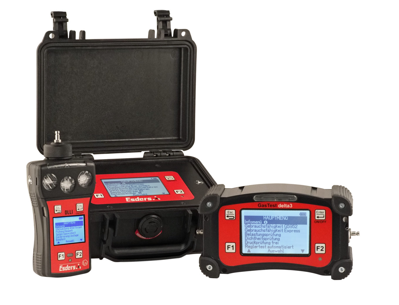
I select the menu option Bump Test in the main menu. First I start with the sensor run-in phase in which the sensors have to be purged in pure air. In the menu point Bump Test, the device is checked for the following: Free flow of the gas paths in the measuring device, Reactivity of the measuring device to test gas, Intact sensors, alarms (optical, acoustic and vibration) First the zero point can be set. Then press Start. The device displays “Please add test gas”. 
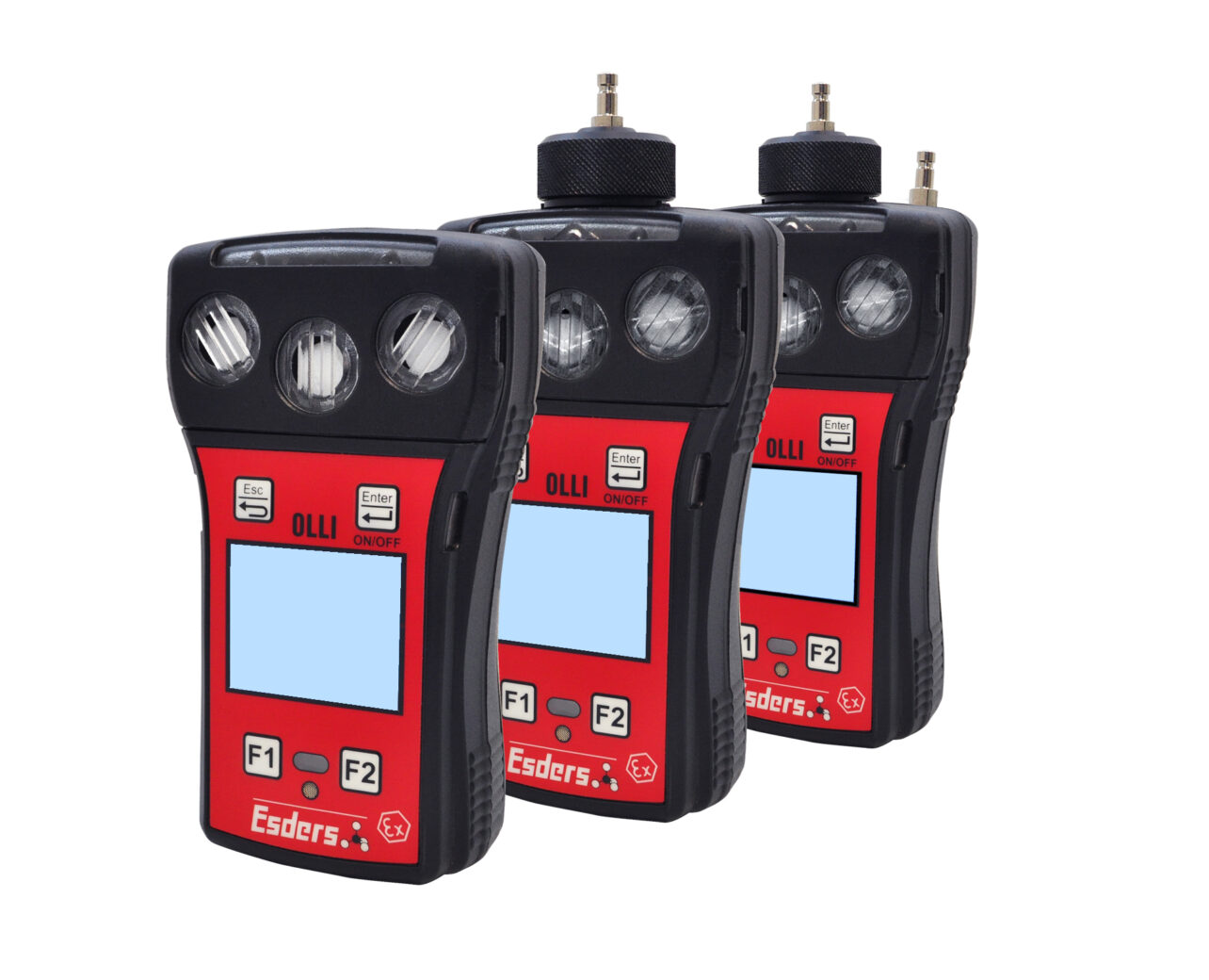
In the case of the OLLI I apply the 5K gas (5 components gas). Test gas can 5 components 1,65 Ltr 35 bar 2.2 % CH4, 150 ppm CO, 2.5% CO2, 15% O2, 25 ppm H2S, rest N2 Capacity: 58 litres Only when the checkboxes are filled in, the bump test is passed and can be verified. The bump test can now be completed with Enter. Please remove test gas. Now the bump test is completed successfully.

The SAFE EthanTest is a special measuring device, which was designed and optimised exclusively for the analysis of gas samples (for methane and ethane). It has 2 internal pumps and a protocol printer. An essential point for high-quality analysis is the heated separation column. This ensures stable analysis results independent of the ambient temperature. The SAFE EthanTest (SAFE stands for Safe Analysis for Ethane) and other measuring instruments for ethane analysis contain a chromatographic separation column in which the gas sample is broken down into its components and passed through with a time delay. The small molecular methane is the first to reach the sensor and is displayed. After a certain time delay, ethane follows, if it is natural gas. Ambient air is used as the carrier gas for transporting the sample. A pump forces the sample through the column.

You use a gas-phase chromatograph to analyse ethane. What does a gas chromatograph do? – The SAFE EthanTest and other measuring instruments for ethane analysis contain a chromatographic separation column in which the gas sample is broken down into its components and passed through with a time delay. The small molecular methane is the first to reach the sensor and is displayed. After a certain time delay, ethane follows, if it is natural gas. Ambient air is used as the carrier gas for transporting the sample. A pump forces the sample through the column.

Nice to know

Nice-to-know
The correct use of probes – Why is it reasonable to use different probes for pipeline inspections? When do I use a carpet probe, bell probe or triangle probe? While in Germany and neighbouring countries in urban areas with paved surfaces mainly carpet probes are used, in unpaved areas, such as meadows and fields, the bell probe is usually preferred. In Asian countries the procedure is quite different, e.g. with the triangle probe. To make clear which disadvantages can occur when using the triangle and bell probe compared to the carpet probe, we have made an experiment. The wind has a great influence on our measuring result. A probe should therefore always be placed exactly on the ground so that the wind cannot mix with the escaping gas and “dilute” the concentration. How strong the wind influences our measurement results – we show in the video with a test, which we carried out at our test track in Haselünne with the explosion-proof multi-range gas measuring device OLLI and the bell probe.

The pigging procedure is the solution for an air-free pipeline. The pig (pipeline inspection gauge) is a synthetic body, which lies tightly against the wall, is pushed through the pipeline with the medium water. Due to the space-filling closure up to the pipe wall, any air present is also pushed through the pipe and can escape at the other end of the pipe. The pig is also removed from the pipeline at this location. The pipeline is then completely filled with water and almost free of air. Only very small residual amounts of air, e.g. at pipe connections, can remain. There are numerous different sizes of pigs, depending on the requirements of the pipeline. The plastic material used, e.g. foam, varies in softness and flexibility An “air-free” filled pipeline is crucial for a successful pressure test!

CONFIGURAÇÃO DE PRIVACIDADE
Durch Aufruf unser Onlinepräsenzen in sozialen Netzwerken

Durch das Aufrufen unserer Onlinepräsenzen in sozialen Netzwerken werden auch dort von Ihnen personenbezogene Daten von dem jeweiligen Anbieter verarbeitet. Bitte beachten Sie, dass Sie genauen Umfang, Zweck, Rechtsgrundlage, Speicherdauer und Ihrer Rechte bzgl. dieser Verarbeitungsvorgänge Ihrer personenbezogenen Daten auch den Angaben des jeweiligen Anbieters entnehmen müssen.

Durch Einbindung von Diensten Dritter

Aufgrund der Einbindung von Diensten Dritter auf unserer Webseite könnten personenbezogene Daten von Ihnen durch den jeweiligen Anbieter verarbeitet werden. Bitte beachten Sie, dass Sie dann Umfang, Zweck, Rechtsgrundlage, Speicherdauer und Ihrer Rechte bzgl. dieser Verarbeitungsvorgänge Ihrer personenbezogenen Daten auch den Angaben des jeweiligen Anbieters entnehmen müssen.

keyboard_arrow_up